Red Jacket Control Box Wiring Diagram
Service spill elimination. Suggested Wiring Diagram without Optional Control Box 20 Figure 17.

3 Way Dimmer Switch For Single Pole Wiring Diagram Wiring Diagram Three Way Switch Dimmer Switch
Newly designed features of The Red Jacket STP are.

Red jacket control box wiring diagram. This control box is designed to operate from 200 to 250Vac. It also describes how to adjust the Pressurstat. If 3 control boxes have gone out with no other reason for it I would think the pump motor to be suspect.
All 3-wire submersible pumps from 13 up to 1 HP utilize a QD control box to. Goulds CB RJ CB RJ - FE Type Control Box 05 115 CB05411 2801044915 00043 G - 50F301CB QD 05 230 CB05412 2801054902 00044 G - 50F311CB. Inspect the control boxs wiring diagram located on the back of the lid.
The Red Jacket Standard Control Box is the simplest way to control site fueling. 230 Vac Remote Control Box with 110 Vac Coil Cap -. Conduit box wiring 19 Figure 15.
It interfaces between the fuel dispenser and the turbine pump and has an indicator. Maintain safe reliable efficient fuel flow the Red Jackets most basic submersible turbine pump interface. CONTROL BOX CROSS REFERENCE New Control Box s Old Model Numbers Control Replaces Replaces Replaces Red Jacket Box HP Volts CentriPro Brand F.
The Red Jacket STP fits 4-inch NPT threaded thin-wall risers and is available in a wide variety of horsepowers. Three phase motors require a magnetic starter with Class 10 overload protection. PLLD System and Pump Control Diagram for Non-Red Jacket Relay Control Box.
Kg 50C201 5 115 110 279 192 87 50C211 2-wire5 230 110 279 192 87 75C211 PSC. Red Jacket Maxxum Big-Flo Single-Phase Wiring 5-5 Figure 5-5. Did you make sure that the new control box was wired according to its installation diagram.
The Red Jacket submersible turbine pump STP is engineered for advanced environmental protection serviceability safety and flow. Service spill elimination. The wires from the pressure switch connect to the electrical input terminals usually called L1 and L2.
Single phase motors and controls franklin qd control box 1 2 hp 115v deluxe submersible motor electric 230v wiring diagram 2801044915 5 115 2823018310 3 wire red jacket well pump home vs 4 switch for 10 subtronic manual engl pdf 2hp crc danfoss vlt aqua full a free troubleshooting 91112011 rm2 series jet 0 208 test diy how to install installation operation 2007 user s intelligent soft starter 5hp. Compare the diagram on the first one that went bad to the replacement diagrams to make sure you arent causing the problem by incorrect wiring. Control box is required with 3 wire single phase units.
Maximum pressure applied to line when testing should not exceed 50 psi. The Red Jacket submersible turbine pump STP is engineered for advanced environmental protection serviceability safety and flow. Red Jacket Submersible Pumps 39 - 4 Floats Switches 43.
In this video Chris shows you how to wire the Franklin Electric QD Control Box. The correct teleflex omc type 479 throttle and shift control cables are available in a. Chapter 2Installation provides safety notices and gives step-by-step instructions for installing and wiring the pump tandem pumps and control boxes.
The Standard Control Box interfaces between the fuel dispenser and the turbine pump and has an indicator light that signals when a customer begins fueling. Red Jacket Maxxum Big-Flo 3-Phase Wiring 5-5 Figure 5-6. Newly designed features of The Red Jacket STP are.
All RED JACKET catalogs and technical brochures. Red Jackets Standard Control Box with 115 VAC Coil for all single-phase 13 1 and 2 HP motors is the simplest way to control site fueling. The control panel is the automated command center for the Jet Residential Wastewater treatment system.
Red Jacket gasoline pumps are designed for Class 1 Group D atmosphere. Chapter 1Red Jacket Quantum Submersible Pump describes the basic components of the system. 230 Vac Remote Control Box with 110 Vac coil - Model 880-041-5 20 Figure 16.
CENtriPro 4 SiNglE-PhASE MotorS Red Jacket Type HP Volts Length Weight No. Red Jacket IQ Smart Controller Box. The wiring diagram identifies the electrical terminals and lists their functions.
Maintain safe reliable efficient fuel flow with Red Jackets most basic submersible turbine pump interface. The Red Jacket IQ Control Box is a smart STP controller solution that provides operators with simplified pump management and unparalleled protection against downtime. Since the submersible turbine pump is powered by the M1 and M2 terminals and M3 terminals -058 -059 models.
At your keyswitch wiring is a yellow or yellowred stripe wire that attaches to one of the control wires and the other control wire is fastened to the s terminal on the switch. Its components and wiring are protected within a lockable corrosion resistant ultraviolet-stabilized thermoplastic enclosure with removable flanges. The Red Jacket STP fits 4-inch NPT threaded thin-wall risers and is available in a wide variety of horsepowers.
Normally well drillers know their stuff when it comes to well pumps and would not give you a non compatible control box. While viewing the wiring diagram Figure 1 or inside the enclosure lid connect the input power L1 and L2 wires to the terminal block labeled TB1. PARTS LIST EXTRACTA MODELS RED P33R1 P75S1 P150S1 Current Models Manfactured after 1963.
Red Jacket gasoline pumps are designed to run at 3450 RPM. Vintage outboard control box syncro drive ace boat co.
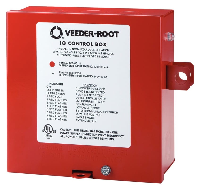
Red Jacket Iq Smart Controller Box Veeder Root

St01 Delay Timer Electrical Circuit Diagram Timer Electronic Schematics

Curtis Sno Pro 3000 Truck Side Wiring Kit Control Harness Power 2 Plug 1uht Snow Plow Wiring Diagram Diagram
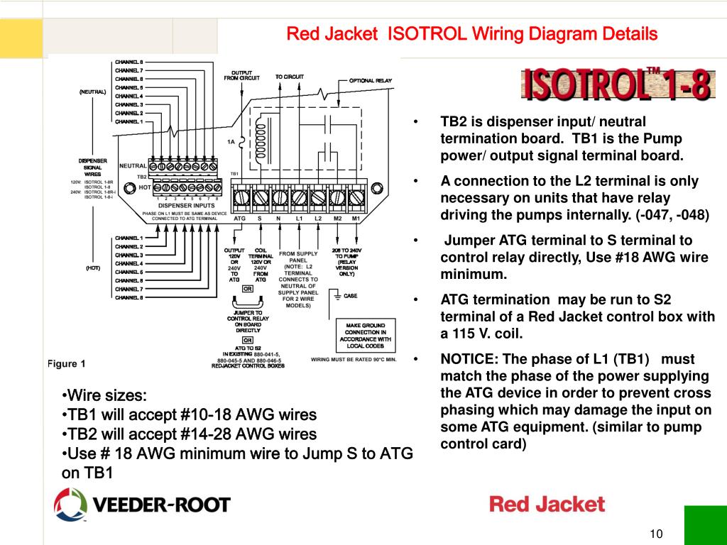
Diagram Red Jacket Wiring Diagram Full Version Hd Quality Wiring Diagram Dmdiagram Amicideidisabilionlus It
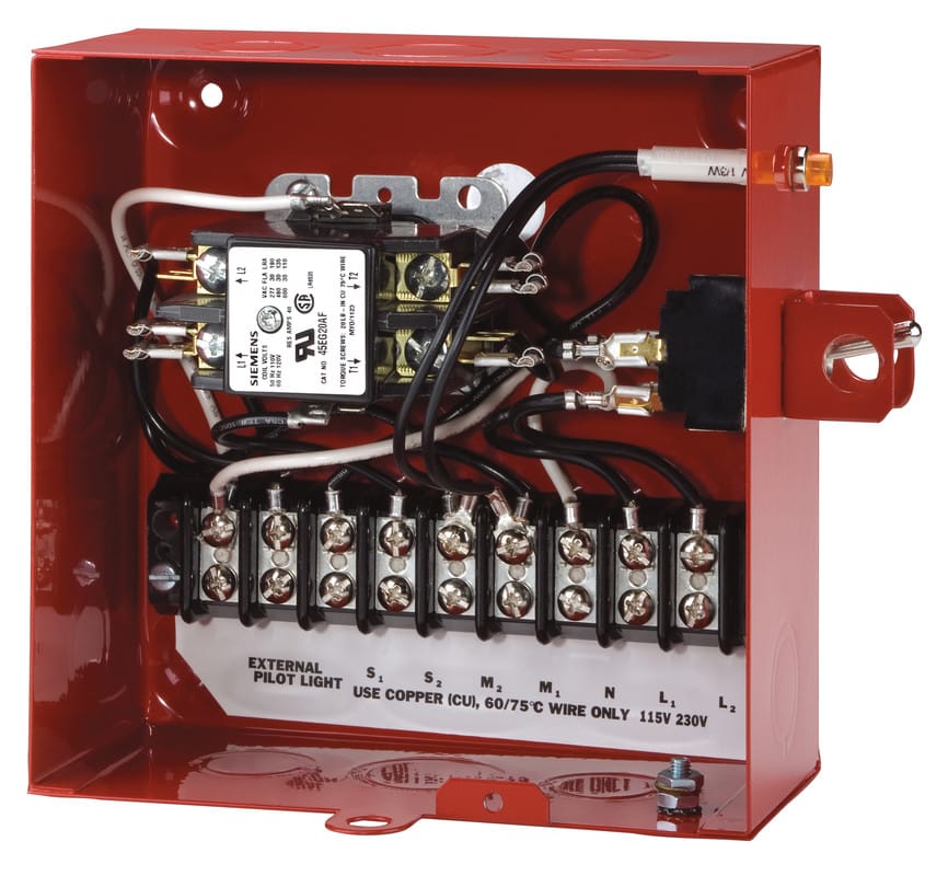
Red Jacket Standard Control Box Veeder Root

8 Cycle Engine Wiring Diagram

Msd Distributor Wiring Diagram Diagram Wire Electrical Problems

Pin On Diagram

Submersible Pump Control Box Wiring Diagram For 3 Wire Single Phase Submersible Pump Electrical Circuit Diagram Submersible

Toyota 5a Engine Wiring Diagram And Wiring Diagram And Ecu Control Box Number Electronic Schematics Engine Diagram Diagram

Wiring Diagram Of Control Panel Box Of Submersible Water Pump

Wiring Diagram For 220 Volt Submersible Pump Http Bookingritzcarlton Info Wiring Diagram For 220 Volt Submersible P Jet Pump Submersible Well Pump Well Pump

Wiring Diagram Ac Generator Valid Modern Dc Wiring Gallery Circuit Diagram Electrical Circuit Diagram Wiring Diagram

Pin On Audio
Collection Of Jeep Grand Cherokee Wiring Diagram Index Of Wiring Diagrams 5 Pin Power Window S Wiring Diagram Electrical Diagram Electrical Circuit Diagram

Instrumentation Loop Diagrams Instrumentation Tools Piping And Instrumentation Diagram Control Systems Engineering Diagram

Engine Indicator Diagram Yamaha

Submersible Motor Control Box Connection Youtube

How To Wire Usb Connector Usb Wire Diagram Instruction Download Usb Design Usb Usb Type A