08 Avalanche Parking Brake Assist Wiring Diagram
It would be really help full to have a wiring diagram of the park assist circuit for this. Parking Aid Rear Sensor 1 Left Middle Circuit Short to Battery DTC B0959 06.

Diagram Wiring Diagram Y15zr Full Version Hd Quality Diagram Y15zr Diagramrt Teatrodelloppresso It
Takes professional type scanner to read these DTCS DTC B0958 01.

08 avalanche parking brake assist wiring diagram. Electric Trailer Jack Wiring Diagram Download. Remove the lid from the electrical center. These areas have been identified in the field.
With the ignition turned OFF short the rear parking assist diagnostic connector to ground while the vehicle is in PARK. Wiring Diagram For Stock Trailer Refrence Lovely Trailer Wiring. To order new harnesses for service or repair refer to Parts Bulletin 54-018.
As the brake pedal is applied the DLC wiring harness may rub on the adjustable pedal motor and short out. ACTROS Pressure Sensor Parking Brake Circuit Diagram. Place foot on the brake.
Click on the image to enlarge and then save it to your computer by right clicking on the image. Remove the 2 philips screws from the bottom. Equipped with Parking Assist RPO UD7 or UFR Supercede.
Additional vehicles 1995 each 5-year 4995 subscription. In the past when cars were simpler diagrams were simpler. Parking Aid Rear Sensor 1 Left Corner Circuit Short to Ground or Open DTC B0958 08.
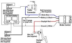
Break the tape on the redblack wire and pull it toward the front of vehicle. How to use this diagram system Use the diagram to locate where on the chassis the connections will be located. Collection of electric trailer brake wiring schematic.
1923 chevrolet car wiring 846 KB 1923 chevrolet general wiring 321 KB 1923 chevrolet superior model 290 KB 1923 chevrolet wiring 237 KB 1925 chevrolet superior model series k 910 KB 1927 chevrolet capitol and national 365 KB. Remove the left dash fuse block cover. The parameter should change between Active and Inactive.
Parking brake is configured. Trace the wiring till you can see where a short may have taken place. Parking Aid Rear Sensor 1 Left Corner Circuit Incorrect Period DTC B0959 01.
The gray and dark blue are paralleled to each sensor and the other four colors are what you are checking against. Some locations are approximate due to wheelbase differences. For the location of the rear parking assist RPA diagnostic connector refer to Object Detection Component Views.
Observe the scan tool Park Assist Switch parameter while pressing and releasing the park assist disable switch. After completing the under dash connections to the electric brake controller open the hood and locate the red wire that is taped to the harness between the underhood electrical center and the driver side front fender. In order to prevent electrical interference from degrading the performance of the connected components you must maintain the proper specification when making any repairs to the twisted-pair wires shown.
The BODY CONTROL MODULE is under the dash left side above the parking brake pedal area. Highlight the individual circuit using a different color for positive and negative. All system wiring diagrams are available in black and white format and may be printed depending on your program settings and available printer hardware.
Wiring diagram index name description page aa power distribution frc 3 ab power distribution frc 4 ac power supply circuit protection 34 ef 5 ad power supply circuit protection 44 ef 6 ae grounding 7. This lever relay is located on the DRIVER SIDE frame rail near the transmission. Coaches which have BOTH the Autopark on the shift lever PARK position as well as a manual foot pedal for the parking brake located to the left of the steering column will have two levers.
ML320 W163 Brake Assist Circuit Diagram ML320 W163 Anti-theft Circuit W Auxiliary Alarm Schematics. Later versions which have NO foot pedal. Adjustable pedal motor.
Parking Aid Rear Sensor 1 Left Corner Circuit Short to Battery DTC B0958 06. Parking Aid Rear Sensor 1 Left Corner Circuit Signal Invalid DTC B0958 21. Turn ON the ignition.
Following is a list of common areas where the High Speed GMLAN wiring may have been shorted chaffed pinched terminals backed out or poor pin fit. Not all connections shown in the diagram will be on any one specific vehicle. ZThe wires must be twisted a minimum of 9 turns per 31 cm 12 in as measured anywhere.
Please discard Corporate Bulletin Number 08-08-127-001A Section 08 - Body and Accessories. One meter lead goes to either gray or dark blue the other to each sensor. Shift the vehicle into REVERSE within 5 seconds.
We have 191 Chevrolet Vehicles Diagrams Schematics or Service Manuals to choose from all free to download. This bulletin is being revised to clarify the text in the Condition Cause and Correction sections and update the Warranty Information. In most cases their diagrams are right from the factory manuals.
MERCEDES BENZ W210 Wiring Diagrams 1995-2001 W210 Starter and Generator Engines 104 111 604 605 606 Wiring Diagram W210 Speed Signal of the Front Axle GES Engines 104 111. Additional vehicles 3495 each Which one should YOU choose. Wires were covered with shielding install new shielding.
First find the problem area on the wiring diagram. All components were connected by wires and diagrams seldom exceeded 4. If the parameter does not cycle between the specified values refer to Park Assist.
To get to it remove the 10mm bolt that holds the parking brake release lever to the trim. Ensure the ignition switch is in the OFF position. There are many different ways to look at fixing an electrical problem but we will stick with the easiest way.
What Are The Standard Brake Controller Wire Color Codes Etrailer Com
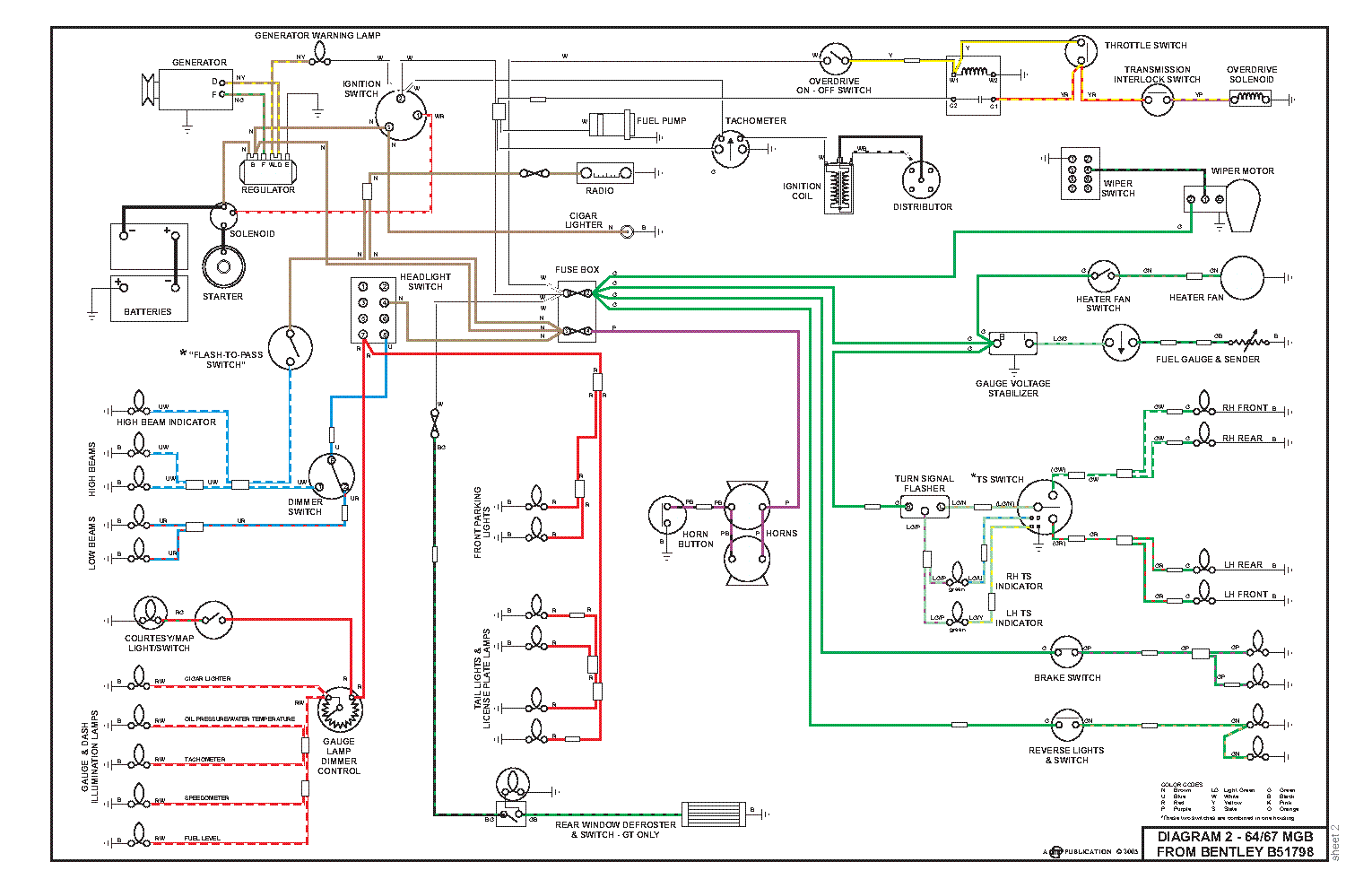
Diagram E30 Bentley Wiring Diagram Full Version Hd Quality Wiring Diagram Diagramman Prolococusanese It
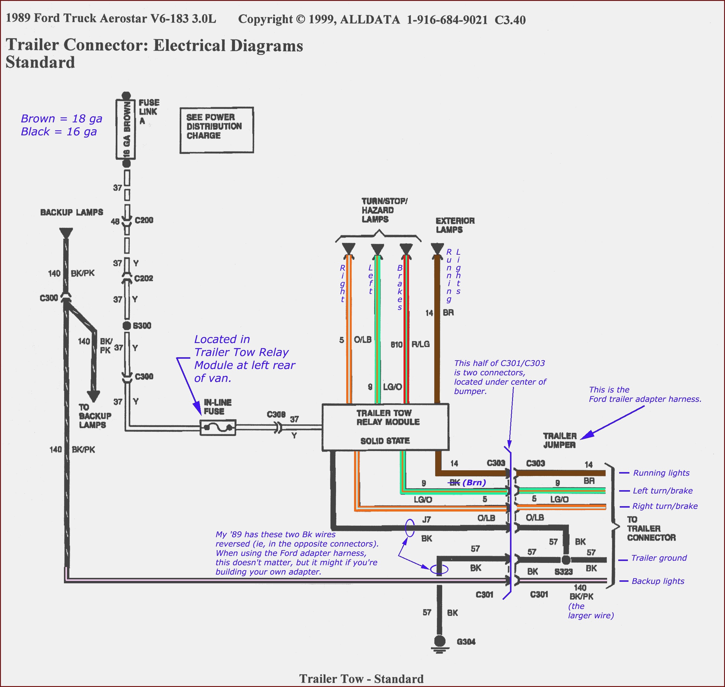
Diagram Wiring Diagram For Fesler Led Tail Light Full Version Hd Quality Tail Light Ipdiagram Amicideidisabilionlus It
Diagram 99 F350 Wiring Diagram Full Version Hd Quality Wiring Diagram Snadiagram Segretariatosocialelatina It


Diagram Bmw 3 Gt Wiring Diagram Full Version Hd Quality Wiring Diagram Diagramhs Segretariatosocialelatina It

Diagram Wiring Diagram For 2008 Chevy Suburban Full Version Hd Quality Chevy Suburban Diagrammd Prolococusanese It

Diagram Dodge Ram Brake Controller Wiring Diagram Full Version Hd Quality Wiring Diagram Lendiagram Amicideidisabilionlus It

Diagram 2014 F 250 Wiring Diagram Full Version Hd Quality Wiring Diagram Dmdiagram Amicideidisabilionlus It

Diagram 95 Gmc Wiring Diagram Full Version Hd Quality Wiring Diagram Dmdiagram Amicideidisabilionlus It

Diagram Rv Brake Wiring Diagram Full Version Hd Quality Wiring Diagram Diagramman Prolococusanese It
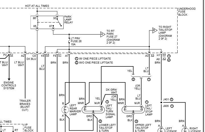
Diagram 2002 Avalanche Tail Lights Wiring Diagram Full Version Hd Quality Wiring Diagram Mmcdiagram Amicideidisabilionlus It
Diagram Suzuki Lets User Wiring Diagram Full Version Hd Quality Wiring Diagram Diagramman Prolococusanese It

Diagram 2001 Chevy Tahoe Ke Turn Backup Wiring Diagram Full Version Hd Quality Wiring Diagram Jobdiagram Amicideidisabilionlus It
Diagram 4g15 Wiring Diagram Full Version Hd Quality Wiring Diagram Diagramrt Teatrodelloppresso It

50 Best Of Brake Light Wiring Diagram Chevy Chevy Silverado Wiring Diagram 2006 Chevy Silverado

Diagram Honda Jazz 2008 Wiring Diagram Full Version Hd Quality Wiring Diagram Trudiagram Amicideidisabilionlus It

Diagram Map Ecu Wiring Diagram Full Version Hd Quality Wiring Diagram Buydiagram Segretariatosocialelatina It
Diagram 1989 Subaru Wiring Diagram Full Version Hd Quality Wiring Diagram Diagramman Prolococusanese It

Diagram Ltr 450 Wire Diagram Full Version Hd Quality Wire Diagram Diagramrt Teatrodelloppresso It