1.5 Hp Submersible Pump Starter Wiring Diagram
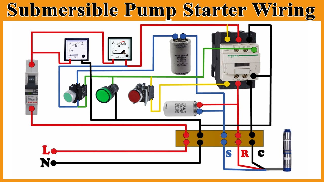
Single Phase Submersible Pump Starter with 2 Pole CPG Contactor and 2 Pole Overload Relay Submersible Pump starters with 2 Pole contactor Relay are specially designed to address Water cooled Submersible Pumps and equipped with a run capacitor and start capacitor. Variety of grundfos pump wiring diagram.

Submersible Motor Control Box Wiring Single Phase Water Pump Water P Submersible Water Pumps Submersible Pump
For pumps 15 hp and smaller allow a minimum of one minute run time per cycle.
1.5 hp submersible pump starter wiring diagram. Single-phase submersible pump control box wiring diagram - 3 wire submersible pump wiring diagram In the submersible pump control box we use a capacitor a resit-able thermal overload and a DPST switch double pole single throw. Panel are available in two models a ECONOMY. Single Phase Submersible Motor Starter Wiring Diagram Fusebox And Schematic Device Id Architects It.
BCH Submersible Pump Starters. Rewire or repair or replace wiring. The diagrams for both the two and three wire pumps can be downloaded using Adobe.
To replace the two wire pump. Submersible pump starter use for starting of induction motor that connected with pump. The material of Fuse wire should be electrolytic tough pitched ETP copper tinned.
Red lion pump wiring diagram Red Lion RL12G10 3W2V 1 HP 12 GPM 3 Wire 230 Volt Submersible Deep Well Pump with Control Box Sump Pumps. For a 30 50 switch this would be 28 lbs. Single phase submersible pump starter wiring diagram Building wiring representations reveal the approximate locations as well as affiliations of receptacles lighting as well as irreversible electric solutions in a building.
Single phase submersible pump starter wiring diagram collections of 4 wire well pump wiring diagram sources. Economy Standard. There are two versions for starter available there.
Goulds pump wiring diagram 2 Wire Submersible Well Pump Wiring Diagram Starter Control Box. For pumps 2 hp and larger allow a minimum of two minutes run time per cycle. As you know that nowadays we use chose submersible.
Lt Mk1 Single Phase Submersible Pump Control Panel At Rs 950 Piece Rajkot Id 10932871462. Day Single Phase Three Phase Up to 3 4 HP 1 HP - 5 HP 7 1 2 HP - 30 HP 40 HP and over 300 100 50 300 100 100. Control Panel For Submersible Molock Pumpset Pump Starter Circuit.
Single Phase Wiring Diagram With Governor Switch. The wiring connection of the submersible pump control box is very simple. May 31 2018 - Single Phase Submersible Pump Starter Wiring Diagram On Water Control Panel Inside To Tagged at B2networkco Log in.
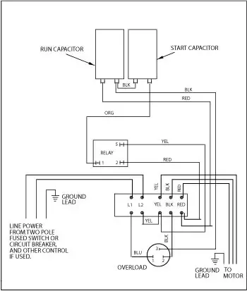
The green ground wire should also be terminated to the box and a ground coming from the panel. Motor maintenance single phase motors controls 1 1 5 hp 282 300 8110 date codes 11c19 newer 1 1 5 hp 282 300 8610 relay l1 l2 yel blk red line power from two pole fused switch or. Click on the image to enlarge and then save it to your computer by right clicking on the image.
These are extremely compact in size and elegant in looks. 3 phase submersible pump motor and electric wiring connection. This will be the complete guide to controlling a three-stage submersible pump motor using magnetic contactors.
Single phase submersible motor. Replace a Two Wire Pump. Here is the complete guide step by step.
Not only a contactor but also i install the thermal overload relay which will protect the motor form burning in case of over current flow to the circuit. BCH make Submersible Pump Motor Starter Panels provide complete solution for the operation protection ible Pump Motors. Single phase motors and controls franklin qd control box 1 2 hp 115v deluxe submersible motor electric 230v wiring diagram 2801044915 5 115 2823018310 3 wire red jacket well pump home vs 4 switch for 10 subtronic manual engl pdf 2hp crc danfoss vlt aqua full a free troubleshooting 91112011 rm2 series jet 0 208 test diy how to install installation operation 2007 user s intelligent soft starter 5hp encapsulated three high thrust standard turbine pumps.
See table page 12 Motor Ratings Maximum starts Per 24 Hr. Loose or broken pump wire. A wiring diagram is a simplified traditional photographic representation of an electric circuit.
A loose wire can cause intermittent pump or other electrical device failures as well as a hard failure that means no power or blown fuses. Shown are breaker magnetic contactor thermal overload protection relay and normally open usually close push button switch. Check wiring against the pump installation manual diagram check all connections for tightness shorts burns damage.
August 9 2018. Single Phase Wiring Diagram for HP pumps With Governor Switch. April 26 2018 by headcontrolsystem.
After determining the voltage is zero disconnect the motor wires directly from the pressure switch box M1 and M2. Grundfos pump wiring diagram Grundfos Pump Wiring Diagram Awesome 177 Best Motor Pinterest. Adjoining cable routes might be shown roughly where specific.
Collection of 3 wire submersible pump wiring diagram. Single phase submersible pump starter wiring diagram Now if you did not know about the star run and common wire in your pump motor then follow the below compressor terminals identifying tutorial and same follow the steps to find out identify submersible pump wires start. Single Phase Wiring Diagrams.
Single-phase motors controls 1 - 15 hp 282 300 8110 date codes 11c19 newer 1 - 15 hp 282 300 8610 relay l1 l2 yel blk red line power from two pole fused switch or circuit breaker and other control if used. Submersible pump wiring diagram Wiring Diagram For Well Pump Pressure Switch Refrence Square D Air Pressor Pressure Switch Wiring Diagram New Wiring. In the diagram I found the 3 pole MCCB.

Aim Manual Page 54 Single Phase Motors And Controls Motor Maintenance North America Water Franklin Electric

Single Phase Submersible Motor Starter Wiring Mcb Type Youtube

Submersible Water Pump Starter Wiring Connection Diagram Youtube

Aim Manual Page 54 Single Phase Motors And Controls Motor Maintenance North America Water Franklin Electric

Aim Manual Page 54 Single Phase Motors And Controls Motor Maintenance North America Water Franklin Electric

Submersible Pump Control Box Wiring Diagram For 3 Wire Single Phase Submersible Pump Electrical Circuit Diagram Submersible

Submersible Pump Control Wiring Diagram Submersible Pump Box Control Wiring Diagram Control Wire Youtube

Three Phase Dol Starter Wiring Diagram Component Single Motor Circuit Contactor Starte Full Size Cont Electrical Circuit Diagram Circuit Diagram Wiring Diagram

10 Electric Motor Reversing Switch Wiring Diagram Wiring Diagram Wiringg Net Circuit Diagram Electrical Circuit Diagram Capacitor

Crompton Dol Starter Wiring Diagram

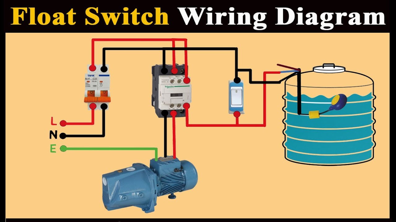
Walnut Innovations Automatic Water Level Controller Water Level Sensors For Single Ph Submersibles Oper In 2021 Submersible Pump Electrical Circuit Diagram Sump Pump
Submersible Starter Connection With Magnetic Contactor Submersible Water Pump Starter Wiring Youtube


Aim Manual Page 54 Single Phase Motors And Controls Motor Maintenance North America Water Franklin Electric
Submersible Starter Connection With Magnetic Contactor Submersible Water Pump Starter Wiring Youtube

Submersible Motor Control Box Wiring Single Phase Water Pump Water Pump Youtube
How To Run A Submersible Pump Using Relays What Relay Configuration Can Be Used Quora

Single Phase Submersible Pump Starter Wiring Diagram Gooddy Org Best Of Submersible Pump Electrical Circuit Diagram Sump Pump

Submersible Starter Connection Single Phase Submersible Starter Connection Youtube