Crest Ultrasonic Wiring Diagram
For example if the object is 20 cm away from the sensor and the speed of the sound is 340 ms or 0034 cms the sound wave will need to travel about 588 microseconds. The ultrasonic cleaner uses high frequency sound waves to create millions of microscopic bubbles Set the ultrasonic cleaning time for example 60 minutes DIAGRAM PARTS LIST Part Description Qty.

Hc Sr04 Ultrasonic Distance Sensor With Arduino Wiring Diagram Schematic Tutorial Arduino Sensor Arduino Projects
Crest Ultrasonics is the worlds leading privately-held manufacturer of ultrasonic cleaning equipment and solutions.

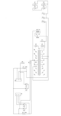
Crest ultrasonic wiring diagram. 1 Energy absorber 2 2 Purge tank 1Ultrasonic Cleaner Reverse-Engineering Codyson CD Jumper OneWiring schematic for Ultrasonic Cleaner - Circuit design - Eng-Tips. Our heavy-duty ultrasonic cleaners have a proven record across a wide range of industry applications with results that outperform conventional cleaning methods uniquely combining speed safety reliability and precise cleaning of even highly complex parts having caked-on residues or rust. It offers excellent non-contact range detection with high accuracy and stable readings in an easy-to-use package.
The enclosure is made of Polycarbonate PC. We have 65 Crest Diagrams Schematics or Service Manuals to choose from all free to download. 12 Volt Switching Power Supply circuit diagram and PCB layout.
Skip to content TOLL FREE. Published by simply admin with June 2 2015. This sensor is a very popular sensor used in many applications where measuring distance or sensing objects are required.
Ultrasonic Sensor in Arduino Code and Wiring Diagram Arduino Projects with Code and WiringSubscribe here for More Source code tutorials. Learn how to use ultrasonic sensor HC-SR04 with Arduino how ultrasonic sensor works how to connect ultrasonic sensor to Arduino how to code for ultrasonic sensor how to program Arduino step by step. The shield connects to ground.
At the conceptual level the operation is pretty straight forward. Ultrasonic sound detector sniffer. 3500s amplifier series 1 MB ca6 ca9 ca12 ca18 series amplifier 3 MB.
The HC-SR04 ultrasonic sensor uses sonar to determine distance to an object like bats do. To view all pictures in Dukane Nurse Call Wiring Diagram images gallery you should follow this particular hyperlink. True RMS Watt Meter.
The wiring diagram below shows you how to connect the HC-SR04 sensor to the Arduino. The detail instruction code wiring diagram video tutorial line-by-line code explanation are provided to help you quickly get started with Arduino. The following diagram indicates the transmitter circuit diagram of the ultrasonic transducer.
800-99CREST 27378 LOCALINTERNATIONAL. The code examples below use digital pin 2 and 3 for the trigger and echo pin respectively but of course you can change this to any digital pin you want. You only need to supply a short 10uS pulse to the trigger input to start the ranging and then the module will send out an 8 cycle burst of ultrasound at 40 kHz and raise its echo.
Always refer to the as-built wiring diagram on the inside door panel for current connection points. We provide a schematic diagram on how to wire the ultrasonic sensor and an example sketch to use with the Arduino. A supply voltage of 12 to 28 VDC is used to power the LVU2700 Series.
Wiring Connecting HC-SR04 to Arduino UNO. HC-SR04 Ultrasonic Sensor - Working. We strive to maintain our position as the leader in ultrasonic cleaning and related technologies by continually improving circuits and components in our equipment.
Ultrasonic-transducer-transmitter The receiver circuit receives the signals after the striking of ultrasonic waves to the object and then convert them to electrical form. The detail instruction code wiring diagram video tutorial line-by-line code explanation are provided to help you quickly get started with Arduino. Schematic of A Typical Ultrasonic Cleaner.
The transducer is made of. Tape back the white and green wires that are not used. At the core of the unit is the piezo-transducer that generates ultrasonic vibrations.
This specific graphic Crest Healthcare Supply in Dukane Nurse Call Wiring Diagram preceding is actually branded using. As shown above the HC-SR04 Ultrasonic US sensor is a 4 pin module whose pin names are Vcc Trigger Echo and Ground respectively. Timing diagram The Timing diagram is shown below.
Ultrasonic HC-SR04 timing diagram. The Echo Pin will output the time in microseconds the sound wave traveled. Learn how to use ultrasonic sensor to control relay ultrasonic sensor triggers light.
The red and black wires connect to terminal points 24 and 13. The module has two eyes like projects in the front. HC-SR04 with Arduino wiring diagram.
The sensor wire is a four wire plus shielded cord. For those on the trail of the DIY Ultrasonic Cleaner this schematic is a good place to start. The Echo is a distance object that is.
Simple voltage booster based on Linear Technologies LT1372 includes PCB design. Electrical wiring of the transmitter should be performed in accordance with all applicable national state and local codes. Two transistor FM transmitter circuit diagram and PCB layout.
Connect 24VDC common to terminal 2 Figure External Wiring Diagrams S83 Download the latest Crest Ultrasonics literature manuals or forms. Download the latest manuals product literature and forms from the Crest Ultrasonics PDF Word library.
Crest Ultrasonic Repair General Science And Electronics Forums 4hv Org

17 Universal Motorcycle Speedometer Wiring Diagram Motorcycle Diagram Wiringg Net Odometer Types Of Electrical Wiring Electrical Circuit Diagram

Crest Old Ca 12 Output Schematic Electronic Circuit Projects Audio Amplifier Electronic Engineering

7 Segment Display Dice Detailed Project With Circuit Diagram Electronic Circuit Projects Electronics For You Circuit Diagram

Ultrasonic Sensor Switch Electronic Schematic Diagram Electronic Schematics Metal Detector Circuit Circuit Diagram

Diagram Wiring Diagram Kiprok Motor Full Version Hd Quality Kiprok Motor Trudiagram Amicideidisabilionlus It

Generatore Ultrasuoni Schema Ultrasonic Ultrasound Ultrasonicleaning Ultrasoniccleaner Check More At Https Www Ultrasonic Ultrasonic Cleaner Technical
Diagram Equalizer Wiring Diagram Full Version Hd Quality Wiring Diagram Diagramman Prolococusanese It

Us10194973b2 Generator For Digitally Generating Electrical Signal Waveforms For Electrosurgical And Ultrasonic Surgical Instruments Google Patents
Us10194973b2 Generator For Digitally Generating Electrical Signal Waveforms For Electrosurgical And Ultrasonic Surgical Instruments Google Patents

Single Phase Inverter Wiring Diagram Download Scientific Diagram

Parts Of A Wave Parts Of A Wave Ultrasound Physics Diagnostic Medical Sonography

Pdf Design Of A Varying Ultrasonic Frequency Amplifier

Us10194973b2 Generator For Digitally Generating Electrical Signal Waveforms For Electrosurgical And Ultrasonic Surgical Instruments Google Patents

Us10201382b2 Surgical Generator For Ultrasonic And Electrosurgical Devices Google Patents

Ultrasonic Sensor Hc Sr04 With Arduino Distance Sensor Object Detector Proteus Simulation In 2021 Sensor Arduino Probe

Us10194973b2 Generator For Digitally Generating Electrical Signal Waveforms For Electrosurgical And Ultrasonic Surgical Instruments Google Patents

Pdf Design Of A Varying Ultrasonic Frequency Amplifier

Pdf Ultrasonic Sensors Based Autonomous Car Parking System